UNDERSTANDING SONET BLSRs


A ring is defined as a set of nodes interconnected to form a closed loop, where fiber cables serve as links.  There are two major types of SONET rings: path-switched and line-switched SONET rings.  Line-switched rings use the SONET line level indications to initiate protection switching. Line layer indications include line layer failures and APS signaling messages that are received from other nodes.  A request for switching may also be initiated via an operations interface. In a UPSR the traffic between two nodes is provisioned to travel either clockwise or counterclockwise under normal conditions. A connection/circuit on a UPSR uses capacity on the entire ring. If both directions of transmission use the same set of nodes and links, the transmission is said to be bidirectional. A connection/circuit on a BLSR uses capacity ONLY between the nodes where

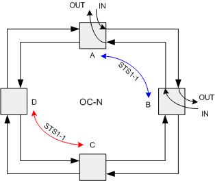
the traffic is added and where it is dropped, see figure 1.


                                                                      Figure 1.


This is much different than the UPSR where traffic between any two nodes consumes bandwidth on the entire.  Again referring to figure 1. we see that if an STS-1 is provisioned between nodes A and B on time slot 1 that time slot will also be available for use between nodes C and D, (STS1-1, STS-1 number1).  This flexibility in the reuse of bandwidth is one of the major advantages of a BLSR.  The price you pay for this flexibility as a user is greatly increased complexity in provisioning and troubleshooting.  Protection against fiber cuts and node failures is done by reserving bandwidth on the ring strictly for protection.  In the BLSR OC-N network of figure 1. exactly one half of the bandwidth, N/2 is available for working traffic between adjacent nodes.  The other N/2 of bandwidth is reserved for protection.  In an OC-48 system time slots 1-24 are used for working traffic and 25-48 are reserved for protection.  At first glance this would seem to be a waste of 1/2 of the system bandwidth.  Upon closer examination it can be seen that this is not the case.  Figure 2 illustrates this fact.  Twentyfour STS-1s are provisioned between node A and B node A’s East span and 24 STS-1s are provisioned between node A and node C on node A’s West span.  Notice that node D is just a pass through node with no traffic being added or dropped.  In fact it would be impossible to add/drop and traffic at node D because the maximum allowed bandwidth, N/2, is allocated as pass through traffic.  In this example of an OC-48 ring 48 STS-1s (ring line rate) have been provisioned and there is no more bandwidth left on the ring.  This is reminiscent of the UPSR case.  In fact in a hubbing scenario the capacity of a BLSR and UPSR are identical and equal to the ring line rate, N.
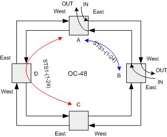


                                                                    Figure 2.


If traffic is not hubbed the BLSR can have a significant capacity advantage over the UPSR.  The extreme case of this is when all traffic is between adjacent nodes.  Figure 3 illustrates this graphically.  The capacity advantage here is 2 times that of a UPSR, or 96. 
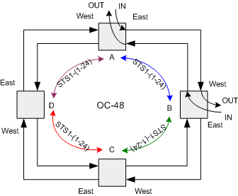


                                                                      Figure 3.

For the case of adjacent node traffic the capacity advantage of the BLSR grows linearly with the number of nodes, however in most cases the traffic will likely resemble a distributed logical mesh still providing a capacity advantage but not quite as extreme as in the adjacent node traffic case. 

Protection Switching in The BLSR

To illustrate the protection switching in a BLSR assume the traffic patter shown in figure 4.  STS-1 number 1 from node A via short path to node B and STS-1 number 2 from node A to node C via pass through node B.
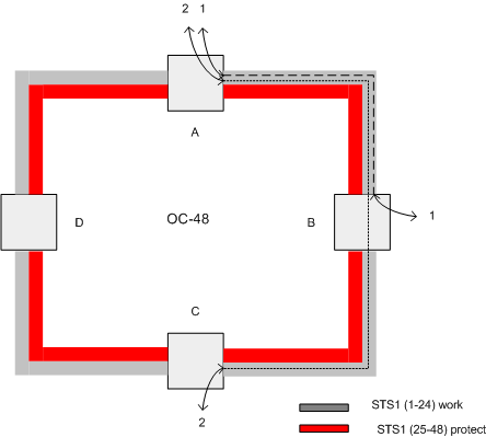


                                                                            Figure 4.


When a cable cut  occurs as shown in figure 5, both nodes adjacent to the cut detect an  LOS and initiate a message sent from a tail-end node, nodes A and B in this case to the head-end node, nodes B and A respectively, requesting the head end perform a bridge of the working channels onto the protection channels, i.e. bridge time slots 1-24 onto time slots 25-48.  This is referred to as a bridge request. The intermediate nodes, on seeing a ring bridge request not addressed to themselves, enter the pass-through mode. The nodes to which the requests were addressed then perform ring switches. The intermediate nodes continue to drop and insert traffic on the working channels as normal.  When the cut is repaired the ring switches back restoring traffic to its original configuration.  

In order to perform a ring switch, the protection channels are essentially shared among each span of the ring. Also, extra traffic may reside in the protection channels when the protection channels are not currently being used to restore working traffic transported on the working channels. With no extra traffic on the ring, under certain multiple point failures, such as those that cause node isolation, services (from the same time slot but on different spans) may contend for access to the same protection channel time slot. This situation yields a potential for misconnected traffic. With extra traffic on the ring, even under single point failures, a service on the working channels may contend for access to the same protection channel time slot that carries extra traffic. This situation also yields a potential for misconnected traffic.  A BLSR prevents traffic from being misconnected by keeping track of the connections in what is known as a squelch table.
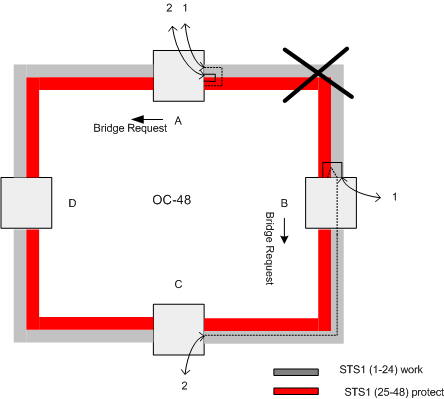
                               

                                                                                    Figure 5.  

Extra Traffic

During fault-free conditions, it is possible to use the protection channels to carry additional working traffic. This additional traffic, which is referred to as extra traffic, has lower priority than the traffic on the working channels and has no means for protection. The extra traffic is set up by provisioning the add and drop nodes for the traffic. Intermediate nodes along the ring are provisioned so that the protection channel STS-1s carrying extra traffic are passed through the node. (Protection channels that are not carrying extra traffic are terminated at the intermediate nodes.) Timeslot assignment of extra traffic on the protection channel will be supported. For rings that support extra traffic, extra traffic is allowed on both sides of the node. An extra traffic STS will be able to enter the ring at any node, and to exit the ring at any node. Nodes that are inserting, dropping, or passing through extra traffic indicate its presence on those spans by inserting the Extra Traffic code in byte K2 bits 6-8. Note that extra traffic has the lowest priority level, and will be pre-empted by any working traffic that requires the use of the protection channels. The transmission of either Idle or Bridged code in byte K2 bits 6-8 is an indication that extra traffic has been removed. When a request of higher priority than the No Request priority is received by the node, and only if that request is a ring request, or requires the usage of the protection channels carrying the extra traffic, extra traffic is pre-empted and squelched on the spans whose protection channels are required for the protection switch. When the affected nodes return to the Idle, K-byte pass-through, or span switching state, extra traffic (on spans whose protection channels are not used for protection purposes) is restored. For Exerciser request, extra traffic is allowed to exist on the protection channels. Extra traffic is also allowed on Locked-out spans.


  SONET Home: www.sonet.com